There are maybe a few hundred people in the world who run Circular Labs Mobius as their primary looper. It is a free AU/VST plugin that runs inside any DAW. Ethan Tufts at Strymon is one of them. He performs as State Shirt, building full arrangements live with Mobius running inside Ableton. When I saw what he was doing, I knew this was the looper. Eight parallel loops. Quantized switching. Half-speed, reverse, multiply. Everything the Echoplex promised but in software.
The problem is controlling it. Your hands are on the guitar. You need your feet. And nobody on earth sells a MIDI foot controller designed for Mobius. Not Strymon. Not anybody.
So here is one. This page contains everything you need to build your own.
The idea
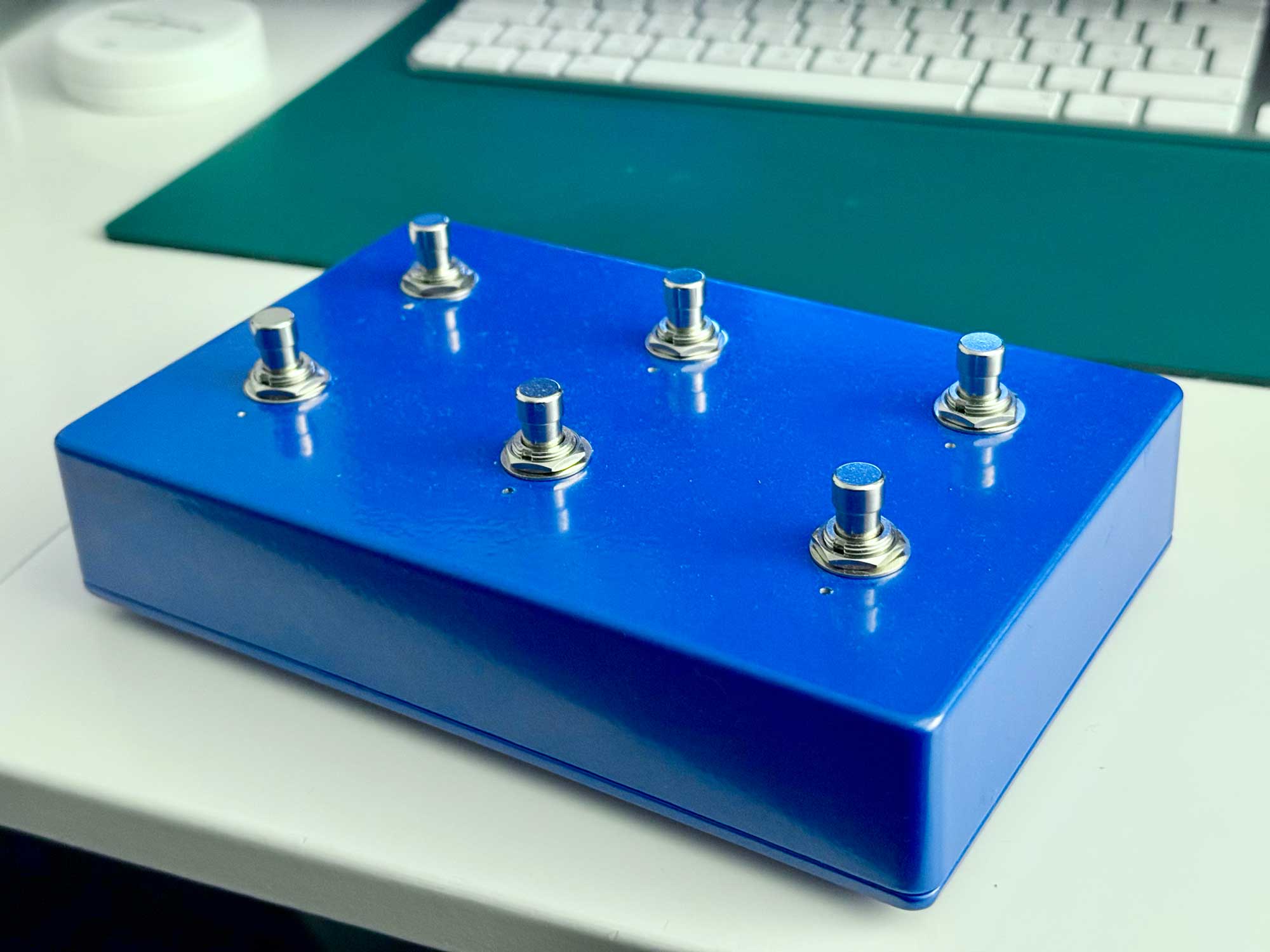
Six footswitches. Each one does three things depending on how you press it. Tap for the primary function. Double-tap for the secondary. Hold for the modifier. That gives you up to 18 distinct MIDI messages from a box the size of a paperback.
An expression pedal controls loop feedback (decay). RGB LEDs show what the looper is doing at any moment. Recording, playing, overdubbing, reversed. You glance down and you know.

The bottom row is the core workflow. Record, overdub, mute. The things your feet reach for most. The top row handles the rest. Undo, multiply, reverse. Double-tap any top row switch to jump between four loops.
Parts
Everything sourced from EU suppliers. Most of the cost is the Teensy and the switches.
| Part | Spec | Qty | Source | Price |
|---|---|---|---|---|
| Microcontroller | Teensy 4.0 (without headers) | 1 | BerryBase / Exp-Tech | ~€30 |
| Footswitches | Momentary Soft-Touch SPST-NO (Banzai SKU 41888) | 6 | Banzai Music | €30 |
| Enclosure | DC-DD Diecast Aluminum 188x120x37mm | 1 | Banzai Music | €12 |
| LEDs | WS2812B strip, cut to 6 individual LEDs (SEZO 1m 60LED) | 1 | Amazon DE | €9 |
| USB panel mount | MEIRIYFA USB-B D-type female to USB-A female | 1 | Amazon DE | ~€7 |
| Internal USB cable | PAXO 30cm USB-A to Micro-B | 1 | Amazon DE | ~€6 |
| Expression jack | 6.35mm TRS stereo panel mount | 1 | Banzai Music | €2 |
| Resistors | 470 ohm x1, 10K ohm x1 | 2 | on hand | – |
| Wire | 22-24 AWG stranded, multiple colors | – | on hand | – |
| Standoffs | M3 nylon for Teensy mounting | 4 | on hand | – |
Total for the electronics is around €95. Most of that is the Teensy and switches.
Alternative suppliers
Reichelt, Mouser EU, and Thomann also carry most of these parts. The footswitches are the hardest to source. You want soft-touch momentary, not the clicky type. The Banzai ones are quiet and feel good under bare feet or shoes.
Tools you will need
Soldering iron, solder, wire strippers, multimeter. A drill with 12mm (switches), 5-8mm (LED holes), 10mm (TRS jack), and 24mm (USB-B panel mount) bits. A deburring tool for the aluminum. A hot glue gun for mounting the LEDs.
Wiring

Pin assignments
| Teensy Pin | Connected To | Notes |
|---|---|---|
| Pin 1 | WS2812B data in | Through 470 ohm resistor |
| Pin 2 | SW1 (Record) | INPUT_PULLUP, other leg to GND |
| Pin 3 | SW4 (Undo) | INPUT_PULLUP, other leg to GND |
| Pin 4 | SW5 (Multiply) | INPUT_PULLUP, other leg to GND |
| Pin 5 | SW6 (Reverse) | INPUT_PULLUP, other leg to GND |
| Pin 6 | SW2 (Overdub) | INPUT_PULLUP, other leg to GND |
| Pin 7 | SW3 (Mute) | INPUT_PULLUP, other leg to GND |
| Pin 14 (A0) | Expression pedal tip | 10K pulldown to GND |
| 3V3 | Expression pedal ring | Reference voltage |
| VUSB | WS2812B VCC | 5V power for LEDs |
| GND | Common ground bus | All grounds meet here |
Notice that the pin numbers do not follow the physical switch layout. Pin 2 is SW1 but Pin 3 is SW4, not SW2. This happened because I wired them in a logical order on the Teensy and a different logical order in the enclosure. The firmware handles the remapping.
Physical layout in the enclosure
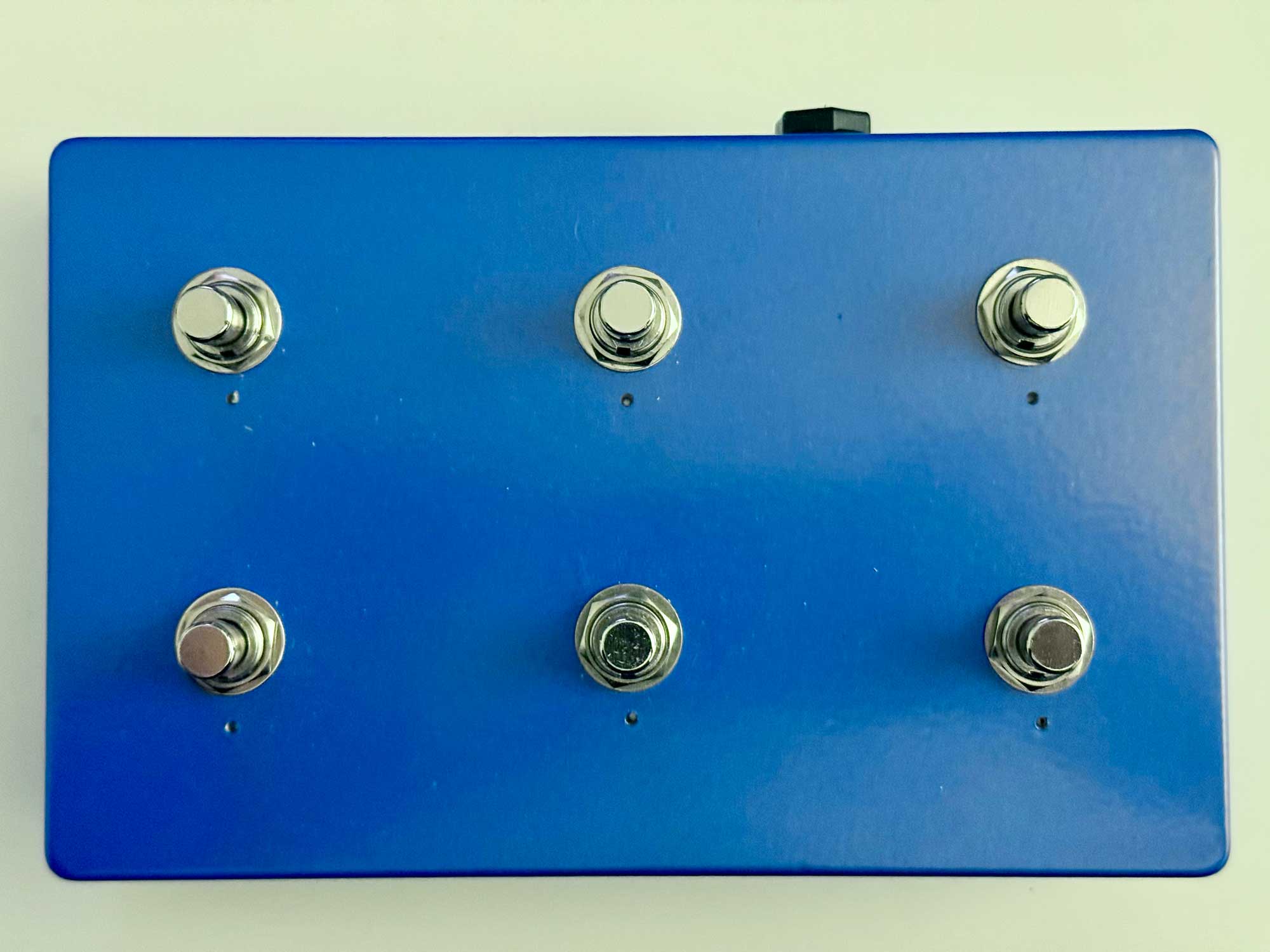
BACK ROW (30mm from top edge)
SW4 (Pin 3) SW5 (Pin 4) SW6 (Pin 5)
Undo Multiply Reverse
FRONT ROW (80mm from top edge)
SW1 (Pin 2) SW2 (Pin 6) SW3 (Pin 7)
Record Overdub Mute
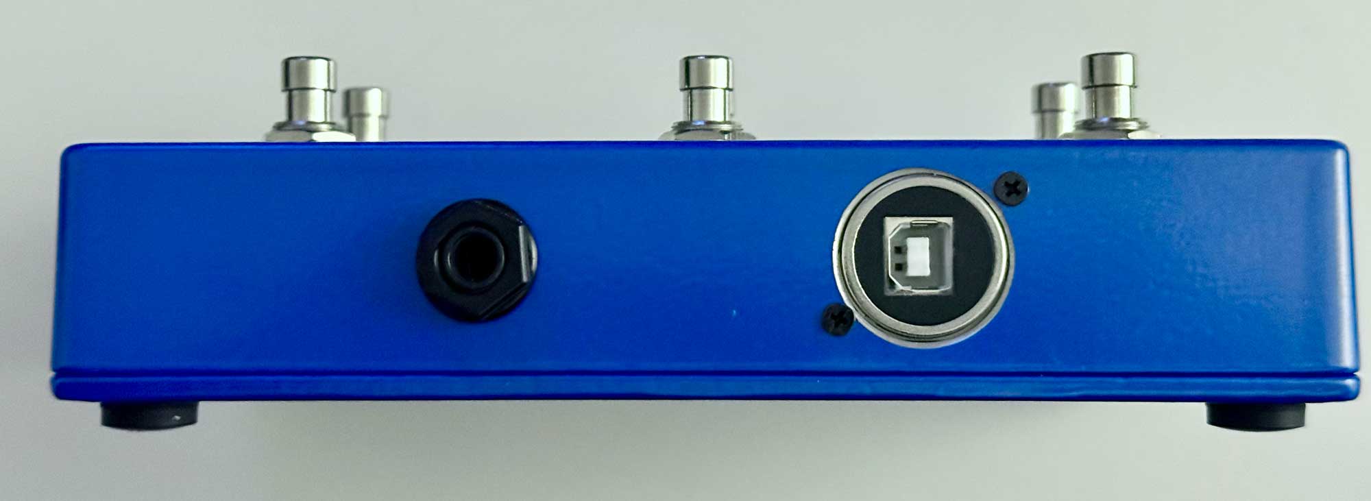
TOP LEFT: USB-B panel mount
TOP RIGHT: TRS expression jack
Connectors
Both connectors mount on the front face of the enclosure. USB-B on the left, expression jack on the right. They sit just below the top edge, visible from the front but barely peeking out from above.
LED chain wiring
The WS2812B strip runs in a snake pattern. Cut six individual LEDs from the strip, keeping the data pads connected. Chain them left to right across the top row, then right to left across the bottom row.
Data in → [LED0] → [LED1] → [LED2]
                                ↓
          [LED5] ← [LED4] ← [LED3]
This means the data order reverses on the bottom row. The firmware maps switches to LEDs with a lookup table:
const uint8_t SW_TO_LED[] = {5, 0, 1, 2, 4, 3};
Mount LEDs in drilled holes above each switch. Hot glue works fine. Keep the data wire runs short.
Ground scheme
Bolt a solder lug to the inside of the enclosure. Scrape the paint at the contact point so you have bare metal for conductivity. Run all ground connections to this single lug:
- 6 switch grounds
- TRS jack sleeve
- Expression pedal 10K pulldown resistor
One wire from the lug to the Teensy GND pin. Star ground. No loops. No noise.
Expression pedal wiring
Standard TRS convention:
- Tip goes to Pin 14 (A0) on the Teensy
- Ring goes to 3V3
- Sleeve goes to GND
A 10K resistor from Tip to GND acts as a pulldown so the pin reads zero when no pedal is connected. Wire the resistor in parallel, not in series.
If your pedal works backwards, swap Ring and Sleeve.
USB connection
The USB-B D-type panel mount provides a standard USB-B socket on the outside of the enclosure. Inside, a short USB-A to Micro-B cable connects the panel mount to the Teensy. This two-part approach is more reliable than a single adapter cable. The USB-B connector is robust and looks like it belongs on audio equipment.
Drill a 24mm hole. The D-type flange mounts with screws.
Firmware
Two files. Clone the repo or drop them into a folder called footswitch_controller in your Arduino sketchbook.
config.h is pin assignments, MIDI CC mapping, gesture timing, LED colors. Change this if your wiring differs from mine. footswitch_controller.ino is the gesture state machine, MIDI I/O, and LED animation engine.
Arduino IDE setup
- Install Arduino IDE
- Install Teensyduino
- Board: Teensy 4.0, USB Type: MIDI
- Libraries: Bounce2, Adafruit NeoPixel
How the gestures work
When someone taps a footswitch and releases it, the firmware cannot send the tap message immediately. It does not yet know if a second tap is coming.
So it waits. For 300 milliseconds. If a second tap arrives in that window, it fires the double-tap. If nothing comes, it fires the single tap. Hold detection runs alongside this. Keep the switch pressed past 500 milliseconds and it fires the hold function immediately, no waiting.
Each switch runs its own state machine independently. No blocking. No delays. All six switches are processed every loop cycle.
300 milliseconds is fast enough that you never feel the delay. Slow enough that double-taps register naturally. I tried 200 and kept misfiring. Tried 400 and it felt sluggish.
LED feedback
The LEDs are not decoration. They are information.
The palette splits along the two rows. Bottom row gets warm tones. Amber when playing. Deep red when recording. Warm white at idle. Top row gets cold tones. Ice blue when an effect is active. Cool white at rest.
The warm and cold split came from the enclosure itself. Metallic blue aluminum. Warm amber and ice blue look right against it. I tried green for “playing” and it looked like a cheap toy.
Animation modes: solid, dim, blink at three speeds, a sine-wave pulse that breathes between 10% and 100% brightness, and a 150ms flash on tap for confirmation. Global brightness sits at 50 out of 255. These are for glancing at in a dim room. Not for lighting it.
MIDI mapping
Tap (primary)
| Switch | CC | Function |
|---|---|---|
| Record | 1 | Start/stop recording |
| Overdub | 2 | Add layers |
| Mute | 3 | Silence loop, keep it running |
| Undo | 4 | Step back one layer |
| Multiply | 5 | Extend loop length |
| Reverse | 6 | Toggle reverse playback |
Double-tap (secondary)
| Switch | CC | Function |
|---|---|---|
| Record | 11 | Clear loop |
| Overdub | 12 | Half-speed (the Ed O’Brien trick) |
| Mute | 13 | Select Loop 4 |
| Undo | 14 | Select Loop 1 |
| Multiply | 15 | Select Loop 2 |
| Reverse | 16 | Select Loop 3 |
Hold (modifier)
Only three switches have hold functions mapped. Record, Undo, and Multiply hold slots are reserved for future use.
| Switch | CC | Function |
|---|---|---|
| Overdub | 22 | Insert |
| Mute | 23 | Pause |
| Reverse | 26 | Speed toggle |
The half-speed on Overdub is stolen from the Ed O’Brien playbook. Record a loop, drop it to half speed, it falls an octave and stretches to twice the length. Layer something on top. Instant Radiohead.
Double-tap the top row switches to jump between loops. Undo, Multiply, Reverse map to Loops 1, 2, 3 left to right. Loop 4 lives on Mute because the top row was full and Mute is the least-used bottom switch during active looping.
Expression pedal
CC 7 controls the feedback parameter. Full toe is infinite repeats. Full heel lets the loop decay. This is where ambient happens.
Mobius configuration
Binding XML
Open Mobius, go to Configuration, then Bindings. Import mobius_bindings.xml or add each binding manually using the Capture button.
<BindingSet name="Footswitch v3" ordinal="0">

  <!-- TAP (CC#1-6) -->
  <Binding name="Record" trigger="control" channel="1" value="1"/>
  <Binding name="Overdub" trigger="control" channel="1" value="2"/>
  <Binding name="Mute" trigger="control" channel="1" value="3"/>
  <Binding name="Undo" trigger="control" channel="1" value="4"/>
  <Binding name="Multiply" trigger="control" channel="1" value="5"/>
  <Binding name="Reverse" trigger="control" channel="1" value="6"/>

  <!-- Expression pedal -->
  <Binding name="feedback" trigger="control" channel="1" value="7"/>

  <!-- DOUBLE-TAP (CC#11-16) -->
  <Binding name="Clear" trigger="control" channel="1" value="11"/>
  <Binding name="Halfspeed" trigger="control" channel="1" value="12"/>
  <Binding name="SelectLoop" trigger="control" channel="1" value="13" arguments="4"/>
  <Binding name="SelectLoop" trigger="control" channel="1" value="14" arguments="1"/>
  <Binding name="SelectLoop" trigger="control" channel="1" value="15" arguments="2"/>
  <Binding name="SelectLoop" trigger="control" channel="1" value="16" arguments="3"/>

  <!-- HOLD (CC#21-26) -->
  <Binding name="Insert" trigger="control" channel="1" value="22"/>
  <Binding name="Pause" trigger="control" channel="1" value="23"/>
  <Binding name="SpeedToggle" trigger="control" channel="1" value="26"/>

</BindingSet>
Manual binding with Capture
If you prefer to set up bindings one at a time:
- Open Mobius, Configuration, Bindings
- Select or create “Footswitch v3” binding set
- Click a function in the left panel (e.g. Record)
- In the Trigger section, set Type to Control, Channel to 1
- Check Capture, then press the corresponding footswitch
- The CC number fills in automatically
- Leave Release unchecked
- Click Save
Session settings
These settings are critical. Without quantization, your loops will drift.
| Setting | Value | Why |
|---|---|---|
| Sync Source | Host | Logic Pro is the tempo master |
| Quantize | Loop | Functions execute at loop boundary |
| Switch Quantize | Loop | Loop switching waits for boundary |
| Subcycles | 4 | Loop divided into 4 sections |
| Empty Loop Action | Copy Timing | New loops inherit length from current |
| Empty Track Action | Copy Timing | Same for new tracks |
| Max Undo | 10+ | Keep plenty of undo layers |
| Mute Mode | Continue | Loop keeps running when muted |
Build sequence
Follow this order. It will save you from rework.
- Test on breadboard first. Wire two switches and two LEDs. Verify MIDI messages appear in a MIDI monitor. Verify LEDs respond. Do not touch the enclosure until this works.
- Solder wires to the Teensy. No headers. Direct solder. This keeps the profile low inside the enclosure.
- Test all six switches and all six LEDs on breadboard. Verify every CC number, every LED index.
- Drill the enclosure. Pilot holes first. 12mm for switches, 5-8mm for LED holes, 10mm for TRS, 24mm for USB-B. Deburr everything.
- Mount panel components loosely. Switches, TRS jack, USB mount. Do not tighten yet.
- Install the ground lug. Scrape paint, bolt it down, check continuity to enclosure.
- Mount the Teensy on nylon standoffs inside the enclosure.
- Wire the ground bus. All switch grounds, TRS sleeve, and pulldown resistor to the solder lug.
- Wire switches to their Teensy pins.
- Wire the LED chain with the 470 ohm resistor on the data line.
- Wire the expression jack. Tip to A0, Ring to 3.3V, Sleeve to ground bus.
- Connect USB panel mount to Teensy via the internal cable.
- Test everything before closing. Every switch, every LED, the expression pedal. Use a MIDI monitor.
- Tighten and close.
Things that went wrong
The USB-C adapter was dead on arrival. I started with an Adafruit 4056, USB-C to Micro-B. Zero power passthrough. Tested multiple cables, multiple orientations. Nothing. The USB-B D-type panel mount turned out to be the better choice anyway. More robust connector. Standard cables.
The 3.3V logic level should not work with 5V LEDs. The Teensy outputs 3.3V. The WS2812B datasheet says it needs a minimum of 3.5V for a logic high. A 470 ohm resistor on the data line and short wire runs made it work fine. If you have trouble, add a 74AHCT125 level shifter. I bought one and never needed it.
10ms debounce is plenty. I expected to need 20ms with these soft-touch switches. Never saw a single double-trigger at 10.
What I would do differently
Label the switches. I have the layout memorized now, but that took a week. An engraved faceplate or even a printed overlay would help anyone picking it up for the first time.
Add LED diffusers. The raw WS2812B LEDs are point sources. Even at low brightness they are a bit harsh. A small frosted cap over each one would soften the light considerably.
Consider MIDI DIN output for hardware that does not speak USB.
Go build one
Everything on this page is everything you need. The parts, the wiring, the firmware, the Mobius configuration. If you build one, or build something better, I would like to hear about it.